What Are the Top Marine Fender Types in 2026?
Marine Fenders protect vessels, quay walls, and other structures when ships approach or remain alongside. In 2026, the right choice still depends on practical site conditions, not a product label or trend. Vessel size, berthing speed, tidal range, and available space all affect how a fender performs. A compact harbor berth may need a different solution from an exposed terminal serving large ships.
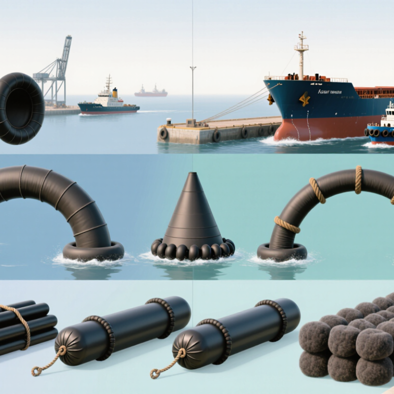
Common options include solid rubber cell and cone fenders, arch and cylindrical designs, pneumatic fenders, and foam-filled units. Each type balances energy absorption, reaction force, installation needs, and maintenance in a different way. Some systems suit fixed quays; others can be more useful where vessel sizes vary or contact conditions change. Conditions vary. A specification that looks strong on paper may still be unsuitable if the fender’s dimensions, panel arrangement, or anchoring do not match the berth.
This guide compares the leading marine fender types by their typical applications, strengths, and trade-offs. It also explains which details buyers should verify, including rated performance, materials, protective panels, and service requirements. Product data and recognized testing methods can help inform a decision, but they do not replace a site-specific engineering assessment. Fit matters. Even experienced teams may need to revisit assumptions when field conditions differ from drawings. By understanding these distinctions, port operators, designers, and procurement teams can ask better questions and select a system suited to both the vessel and the structure.
Begin with PIANC WG33: How Vessel Mass and Approach Speed Define Berthing Energy
Marine fender selection in 2026 should begin with berthing energy, not a catalogue table.
PIANC WG33 provides a widely used framework for estimating it. The basic relationship is simple: energy rises with effective vessel mass and with the square of approach speed. Effective mass accounts for the vessel’s displacement and the surrounding water that moves with it. Speed should reflect the component directed toward the berth, not just the vessel’s speed along the channel.
That distinction matters. A loaded cargo vessel and the same vessel in ballast can present different design cases. A small increase in approach speed can sharply increase energy demand.
PIANC’s method also applies factors for conditions such as berthing configuration, eccentric contact, and berth geometry. These are not decorative adjustments; they affect the energy a fender system must absorb. Check operating records, vessel particulars, tide conditions, and local approach practices before settling on design inputs.
Field measurements are useful, though they can be sparse or inconsistent. That is an uncomfortable gap, but ignoring it does not make the estimate more reliable.
Once the design energy is established, compare the fender’s rated energy absorption and reaction force with the berth structure’s capacity. A high-energy rating alone is not enough.
Compare Cell, Cone, and Arch Fenders by Rated Energy (kNm) and Reaction Force (kN)
For 2026 berth planning, compare each fender’s rated energy in kNm with its reaction force in kN. These figures must come from the same deflection range and test conditions. A high energy rating alone does not guarantee a suitable installation.
Cell fenders are commonly selected for substantial energy absorption and robust, compact support. Cone fenders can absorb considerable energy while keeping reaction force comparatively controlled, which may help protect a berth structure. Arch fenders have a simpler profile and suit many straightforward installations, but their capacity depends strongly on size and rubber formulation. Check the actual rating curves. Type names are not performance guarantees.
Compare specific models at the expected vessel approach speed, angle, and temperature. For example, a 500 kNm rating paired with a 700 kN reaction force is useful only if the structure can accept that load. Verify panel size, deflection limits, and safety factors against the project design. Small details matter. Catalog values can look neat, while real berthing conditions are less tidy. If operating data is uncertain, revisit the assumptions before choosing a fender.
What Are the Top Marine Fender Types in 2026? — Compare Cell, Cone, and Arch Fenders by Rated Energy (kNm) and Reaction Force (kN)
| Fender type | Indicative size range | Typical rated energy range (kNm) | Typical reaction force range (kN) | Typical rated deflection | Common applications and characteristics |
| Cell fender | Approx. 400–2,000 mm body diameter | Approx. 20–2,500 | Approx. 150–5,000 | About 52.5% | Robust, high-capacity design commonly used at commercial ports and berths handling large vessels. Often paired with a frontal frame and low-friction facing. |
| Cone fender | Approx. 500–2,000 mm body diameter | Approx. 20–10,000 | Approx. 150–10,000 | About 70–72.5% | High energy absorption for its footprint and suitable for a wide range of berthing angles. Commonly specified for container, bulk, and other high-capacity berths. |
| Arch fender | Approx. 150–1,000 mm overall height | Approx. 5–500 | Approx. 50–1,500 | About 50% | Simple, compact, and durable. Often used for small-to-medium berths, quay walls, dolphins, and locations where straightforward installation is preferred. |
Note: These are indicative ranges across commonly available sizes, not guaranteed values for a specific fender. Energy absorption and reaction force are paired performance values that vary with dimensions, rubber compound, deflection, temperature, manufacturing tolerances, and test method. Compare certified performance data for the selected model and design conditions before specifying a fender.
Assess Pneumatic Fenders Against ISO 17357:2014 Performance Requirements
What Are the Top Marine Fender Types in 2026?
Assess Pneumatic Fenders Against ISO 17357:2014 Performance Requirements
ISO 17357:2014 gives buyers a practical basis for assessing floating pneumatic rubber fenders. Check whether the offered unit meets the relevant high- or low-pressure requirements. Compare its stated energy absorption and reaction force at the specified compression, rather than relying on a headline capacity. Numbers matter.
Look closely at dimensions, internal pressure, material quality, and test documentation. The standard includes requirements for construction, inspection, and performance testing. A credible report should identify the tested fender and show results against the applicable criteria. If details are missing, ask how the figures were measured. A neat data sheet is not proof by itself.
Field conditions still matter. Vessel approach speed, berth geometry, water level, and temperature can change how a fender performs in service. ISO compliance helps establish a baseline, but it does not replace site-specific selection or routine inspection. That distinction is easy to overlook. Even a compliant fender can be poorly matched to a berth, and a test report cannot predict every impact. Check the installation plan, pressure records, and inspection schedule alongside the standard.
What Are the Top Marine Fender Types in 2026? Assessing Pneumatic Fenders Against ISO 17357:2014
ISO 17357:2014 defines P50 and P80 pneumatic fender pressure classes, with nominal initial internal pressures of 50 kPa and 80 kPa, respectively. These pressure values alone do not establish compliance: energy absorption and reaction force must also be assessed against the applicable requirements for the fender’s size and type.
Compare Foam-Filled and Cylindrical Fenders by Hull Pressure (kN/m²) and Durability
In 2026, compare marine fenders by hull pressure, not energy absorption alone. Hull pressure is reaction force divided by the effective contact area, expressed in kN/m². A foam-filled fender often spreads contact across a broad, compliant surface, helping limit local pressure when correctly sized. A cylindrical rubber fender may create a narrower contact zone, so pressure on an unreinforced hull can rise. But shape alone does not settle the comparison. Diameter, compression, mounting, and the manufacturer’s test curve all matter.
Check actual figures. For example, a measured reaction force of 300 kN across 3 m² gives 100 kN/m². That calculation is only useful if the contact area reflects real use. A tidy specification can still mislead.
Foam-filled units resist punctures through a tough outer skin, yet cuts or prolonged exposure can compromise that protection. Cylindrical rubber units are mechanically simple and can tolerate repeated contact, though abrasion, cracking, and fastener wear need inspection.
Look for pressure data at the expected compression, then compare it with the vessel’s allowable hull pressure. Recheck after installation; alignment can change the contact patch. Small details count.
Select a Fender System Using PIANC Energy, Reaction-Force, and Clearance Checks
What Are the Top Marine Fender Types in 2026?
Select a Fender System Using PIANC Energy, Reaction-Force, and Clearance Checks
Marine fenders commonly include cell, cone, arch, cylindrical, and pneumatic designs. The right choice depends on berth geometry, vessel range, and operating conditions—not popularity. Start with berthing energy, assessed using PIANC guidance and project-specific assumptions. Vessel displacement, approach velocity, eccentricity, and berth conditions all matter. Small errors in speed estimates can change the result.
Then check the fender’s reaction force at its rated deflection. A system that absorbs enough energy may still impose excessive loads on the quay or vessel hull. Compare the manufacturer’s performance curve with structural capacity and allowable hull pressure. Leave room for uncertainty. Real berthing conditions are rarely as tidy as the calculation sheet.
Clearance is equally practical. Measure the space available behind the panel and around chains, ladders, and mooring hardware. Cone and cell systems can offer substantial energy absorption in compact layouts, while arch units may suit simpler installations. Pneumatic fenders can work well where vessels or water levels vary, but require suitable handling and maintenance. Check movement at low and high tides. Then review installation details with a qualified marine engineer; the first layout is not always the best one.